| pc | ||
| pi1 | ||
| pi4 | ||
| src | ||
| README.md | ||
PI-MC-WATCHER
A system that allows Monitoring of Raspberry PI('s) and it's running Minecraft Server(s) on PC and Mac
What it is about
The system contains of three parts. Those are the PC Module, RPi Master Module and ** RPi Slave Module**
Required for this to work without any modifications are:
- 1x PC or macboock
- 2x Raspberry PI's with GPIO Pins (Model A, A+, B or B+), any version works (I use a Raspberry PI 4 B and Raspberry PI 1.2 B+) and needed power, ethernet, etc. -connections
- 2x cooling fan (I used 1x 5V & 1x 12V fan), external 12V power source (or matching one for the large fan)
- 6x GPIO cables
- fan control pcb with control circuit (The needed circuit is described here)
PC Module
The PC module requests all kinds of system information from both Raspberry PI'S making use of FTP. The Raspberry PI hosts an FTP server from which the PC fetches the text file output.txt containing all infos.
Rpi Master Module
The Rpi Master Module (or Raspberry Pi Master module) gets all sorts of informations from its own system and Minecraft Servers and writes them to the output.txt file. It also gets fanspeed requirments from the RPi Slave Module making use of binary signal transmission over 2 GPIO pins. This module then controls the fan speeds.
RPi Slave Module
The Rpio Slave Module transmits its fanspeed requirments over 2 GPIO pins to the RPi Master Module.
Setup
Raspberry PI basic setup
- Install a UNIX operating of your choice onto both PI's
- If both PI's are different, declare the more powerful one as the master and install an FTP server on it
- Install pytho3 on both PI's
- Go to the releases page and download the latest release.
- Copy the single programs to their dedicated devices
- Make the programs run automatically on launch (optional)
- Edit IP adresses, ports, usernames, passwords, configs, etc... on all 3 programs
- Connect 2 GPIO pins from the Slave on pins
GPIO_17andGPIO_18to the Master pinsGPIO_17andGPIO_18(17 to 17 and 18 to 18) - Connect the GPIO pins
GPIO_4and3.3V OUton both PI'S and pinGPIO_24,GPIO_25and5V outof the Master with the fan control circuit board. For pin mapping, view here. - Connect the cooling fans like shown here
Fan control circuit
This setup includes a custom designed and built circuit board that manages the cooling fans. The board has the following circuit:
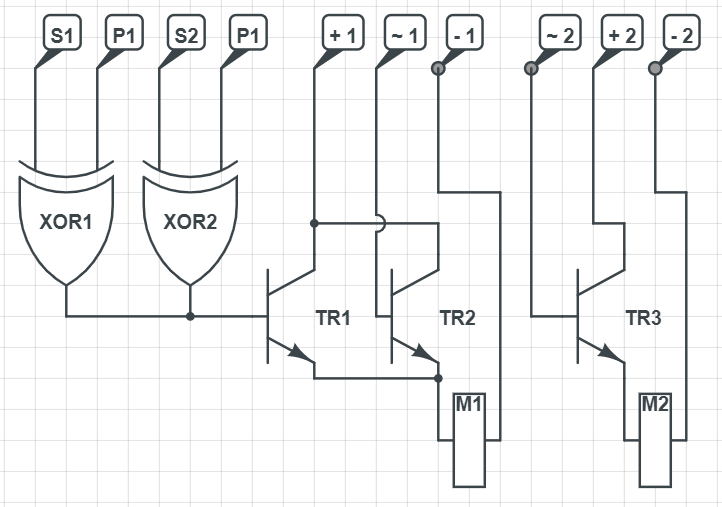
Description
- S1: Status Pin for Master PI. Connected to
GPIO_4 - S2: Status Pin for Slave PI. Connected to
GPIO_4 - P1: Power Pin for Master PI. Connected to
3.3V Out - P2: Power Pin for Slave PI. Connected to
3.3V Out - + 1: 12V external Power supply for large cooling fan
- + 2: 5V Power supply for small coolimg fan. Connected to
5V Outon Master PI - - 1: Ground for 12V external power supply
- - 2: Ground for
5V Outon Master PI - ~ 1: Modulation Pin for large cooling fan. Connected to
GPIO_24on Master PI - ~ 2: Modulation Pin for small cooling fan. Connected to
GPIO_25on Master PI
In-more-depth explanation
//TODO