mirror of
https://github.com/JonasunderscoreJones/PI-server-rack.git
synced 2025-10-23 01:29:18 +02:00
56 lines
3.2 KiB
Markdown
Executable file
56 lines
3.2 KiB
Markdown
Executable file
# WARNING: This file is outdated. Since the last commit, a lot has changed.
|
|
|
|
# pi server rack
|
|
Monitor and control a Raspberry PI server rack.
|
|
|
|
## Why?
|
|
Because I can. Overcomplicated stupid projects are a lot of fun.
|
|
### To "briefly" explain the concenpt:
|
|
A server rack containing 2 Raspberry PI's (Pi 4 & Pi 1.2) and an Arduino Nano is cooled by 2 fans. A display at the front of the rack shows some status infos along with some buttons for direct control of the PI's.
|
|
The Arduino's role is to communicate with the PC that it is connected to via USB for monitoring purposes and to tweak settings from the PC.
|
|
The display is controlled by the arduino.
|
|
|
|
### Required for this to work without any modifications are:
|
|
- 1x PC
|
|
- 2x Raspberry PI's with GPIO Pins (Model A, A+, B or B+), any version works (I use a **Raspberry PI 4 B** and **Raspberry PI 1.2 B+**) and needed power, ethernet for temporary ssh access
|
|
- 2x cooling fan (I used 1x 5V & 1x 12V fan), external 12V power source (or matching one for the large fan)
|
|
- GPIO cables
|
|
- fan control pcb with control circuit (The needed circuit is described [here](#control-circuit))
|
|
|
|
### Setup: *outdated!!!*
|
|
## Raspberry PI basic setup
|
|
1. Install a UNIX operating of your choice onto both PI's
|
|
2. If both PI's are different, declare the more powerful one as the master and install an FTP server on it
|
|
3. Install pytho3 on both PI's
|
|
4. Go to the [releases page](https://github.com/J-onasJones/PI-MC-WATCHER/releases) and download the latest release.
|
|
5. Copy the single programs to their dedicated devices
|
|
6. Make the programs run automatically on launch (optional)
|
|
7. Edit **IP adresses**, **ports**, **usernames**, **passwords**, **configs**, etc... on all 3 programs
|
|
8. Connect 2 GPIO pins from the Slave on pins `GPIO_17` and `GPIO_18` to the Master pins `GPIO_17` and `GPIO_18` (17 to 17 and 18 to 18)
|
|
9. Connect the GPIO pins `GPIO_4` and `3.3V OUt` on both PI'S and pin `GPIO_24`, `GPIO_25` and `5V out` of the Master with the fan control circuit board. For pin mapping, view [here](#fan-control-circuit).
|
|
10. Connect the cooling fans like shown [here](#fan-control-circuit)
|
|
|
|
## Control circuit
|
|
|
|
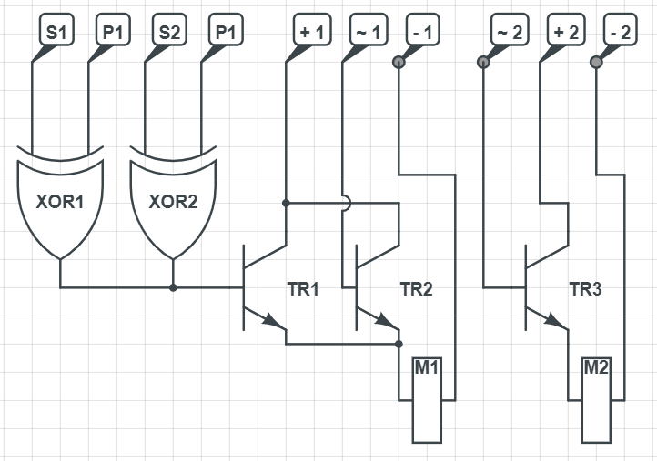
This setup includes a custom designed and built circuit board that manages the cooling fans. The board has the following circuit:
|
|
|
|
|
|
|
|
### Description
|
|
- **S1**: Status Pin for Master PI. Connected to `GPIO_4`
|
|
- **S2**: Status Pin for Slave PI. Connected to `GPIO_4`
|
|
- **P1**: Power Pin for Master PI. Connected to `3.3V Out`
|
|
- **P2**: Power Pin for Slave PI. Connected to `3.3V Out`
|
|
- **+ 1**: 12V external Power supply for large cooling fan
|
|
- **+ 2**: 5V Power supply for small coolimg fan. Connected to `5V Out` on Master PI
|
|
- **- 1**: Ground for 12V external power supply
|
|
- **- 2**: Ground for `5V Out` on Master PI
|
|
- **\~ 1**: Modulation Pin for large cooling fan. Connected to `GPIO_24` on Master PI
|
|
- **\~ 2**: Modulation Pin for small cooling fan. Connected to `GPIO_25` on Master PI
|
|
- **XOR 1**: XOR-Gate 1. Determines Master PI status
|
|
- **XOR 2**: XOR-Gate 2. Determines slave PI status
|
|
- **TR1**, **TR2**, **TR3**: NPN Transistors
|
|
|
|
# In-more-depth explanation
|
|
|
|
//TODO
|